
Stress measurement method and error correction based on polarization camera
-
摘要:
基于Muller矩阵和 Stokes矢量测量原理,提出了一种利用圆偏振光、无旋转元件的应力测量和在线误差校正方法。该方法通过偏振相机获取的光强信息计算出待测样品的相位延迟,对相位延迟进行溯源便可得到样品的应力分布。通过分析标准1/4波片的相位延迟和偏振相机消光比对测量结果的影响,提出了相应的在线测量与校正方法。为验证方案的可行性,搭建了一套应力测量系统,利用该系统测量了一块经计量部门赋值的633 nm波长的1/4波片,并用提出的误差校正方法校正了测量结果。结果表明:校正前后波片相位延迟相对误差分别为11.5%和1.73%,校正后的相对误差主要由线偏振器产生。所提方法具有测量过程简单、精确度高等特点。
Abstract:Based on the Muller matrix and Stokes vector measurement principles, a stress measurement and online error correction method using circularly polarized light and no rotating elements was proposed. The phase delay of the sample to be tested was calculated by the light intensity information captured by polarization camera, and the stress distribution of the sample could be obtained by tracing the phase delay. By analyzing the effect of the phase delay of standard quarter wave plate and the extinction ratio of polarization camera on the measurement results, the corresponding online measurement and calibration method was proposed. To verify the feasibility of the proposed approach, a stress measurement system was constructed. A quarter wave plate with 633 nm wavelength assigned by the metrological service was measured by this system, and the measurement results were corrected by the proposed error correction method. The results show that the relative errors of the wave plate phase delay before and after correction are 11.5% and 1.73%, respectively, and the corrected relative errors are primarily caused by the linear polarizer. The proposed method exhibits characteristics such as simple measurement process and high accuracy.
-
Keywords:
- phase delay /
- stress measurement /
- wave plate /
- polarization camera /
- error correction
-
引言
残余应力的大小是评价光学元件性能的一个重要指标[1],在光学元件生产与制造过程中具有指导性作用。由于制造工艺的制约,光学元件生产中的退火过程会产生一定的应力,内部应力过大会降低玻璃的稳定性和机械强度,加工完成的元件表面还会因为应力的存在而缓慢变形,不仅影响成像质量,也会缩短产品的寿命[2-3]。因此,精确检测光学元件的应力大小和空间分布对于确保其稳定性、安全性及可靠性至关重要[4]。
应力检测的方法主要分为有损检测法和无损检测法。有损检测法如钻孔法[5]、轮廓法[6],在测量残余应力时需要将待测元件切割一部分,通过待测面上应力释放所引起的应变来测量残余应力。这类方法能获取丰富的残余应力分布数据,但是实际操作复杂、检测效率低,而且对材料本身具有不可逆的破环,适用性差;无损检测法如X射线衍射法[7]、偏振感色法、数字光弹法[8]等,这些方法都能通过非接触的手段测得样品的残余应力,其中数字光弹法通过计算应力双折射产生的相位差来获取应力分布,这类方法具有更高的测量精度[9]。数字光弹法又分为偏振光调制法[10]和移相干涉法,偏振光调制法一般采用补偿器、1/4波片等偏振元件来补偿待测样品产生的相位差,从而得到样品的真实应力分布,但是这类方法往往需要多次测量才能保证测量精度;移相干涉法又称光强法,通过待测样品的相位延迟与探测器接收到的光强信息之间的关系来求解相位差。基于移相干涉技术,AJOVALASIT A等人[11]和李金鹏等人[12]都有过研究,该方法需要在测量途中多次旋转1/4波片,无法实现应力的实时检测;在此基础上,高阳等人[13]利用偏振相机测量应力,实现了透明元件应力分布的实时检测,但是该方法基于线偏振光检测,测量结果受样品主轴方位角的影响,实际使用过程中无法有效测量应力分布不均匀的样品;后续唐凡春等人[14]提出利用径向偏振光测量样品,该方法使用涡旋波片对测试光线进行调制,解决了线偏振光测量时受样品主轴方向角影响的问题,虽然可以同时测量波片相位延迟量和主轴方位角,但是该方法无法测量样品的全局应力分布;为解决线偏振光测量受样品主轴方位角影响的问题,万新军等人[15]基于圆偏振光测量了1/4波片的应力分布,并分析了波长失配误差对测量结果的影响,然而未考虑线偏振器和偏振相机消光比对测量结果的影响。
针对以上问题,本文从误差分析的角度出发,阐述了各偏振元件对测量系统的影响因素。通过对偏振测量公式的重新推导,校正了1/4波片的相位延迟和偏振相机的消光比所带来的测量误差。最后选用一块经计量部门赋值的1/4波片作为被测件,由测量与应力值成线性关系的相位延迟量作为替代,验证了方法的有效性。
1 测量原理
在光弹测量领域,通常用单位厚度试样产生的应力双折射光程差$ {\Delta _{\mathrm{n}}} $表示应力大小[16]:
$$ {\Delta _{\mathrm{n}}} = \frac{\Delta }{d} = \frac{{\lambda \xi }}{{2\pi d}} $$ (1) 式中:$ \Delta $表示应力双折射产生的光程差;$ d $表示样品厚度;$ \xi $表示应力双折射产生的相位延迟量;$ \lambda $表示测试光波长。因此,实际测量中对于已知厚度$ d $的样品,只需测量出相位延迟$ \xi $值,即可解算出应力大小。本文讨论的应力测量方法,是测量样品的相位延迟量,由式(1)计算得到应力分布。
在偏振光学领域,通常使用4×4的Muller矩阵(M)表征光学元件的偏振特性,使用4×1的Stokes矢量(S)表示光线的偏振状态,通过矩阵相乘即可得到入射光线$ {{\boldsymbol{S}}_{{\mathrm{in}}}} $经过若干个偏振元件(${{\boldsymbol{M}}_1},{{\boldsymbol{M}}_2}, \cdots ,{{\boldsymbol{M}}_n}$)后的偏振状态$ {{\boldsymbol{S}}_{{\mathrm{out}}}} $。若已知入射光的偏振态和各偏振元件的Muller矩阵,并采集出射光的偏振信息,即可解算出样品的相位延迟,计算原理为[17]
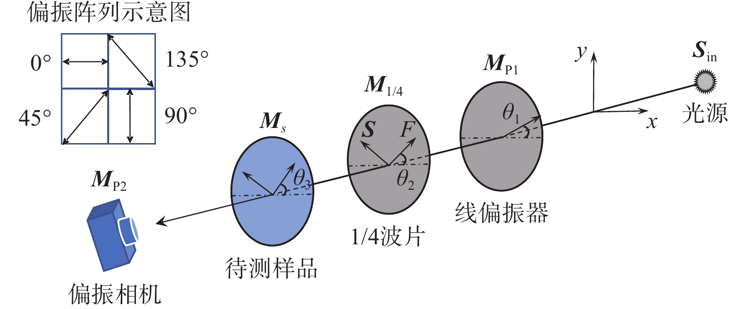
$$ \mathop {\boldsymbol{S}}\nolimits_{{\mathrm{out}}} = \mathop {\boldsymbol{M}}\nolimits_n \cdots \mathop {\boldsymbol{M}}\nolimits_3 \mathop {\boldsymbol{M}}\nolimits_2 \mathop {\boldsymbol{M}}\nolimits_1 \mathop {\boldsymbol{S}}\nolimits_{{\mathrm{in}}} $$ (2) 图1为利用圆偏振光测量波片相位延迟量和应力方向角的原理示意图。
取入射光的传播方向为z轴,线偏振器、1/4波片、待测样品、偏振相机的主轴方位角分别为$ {\theta }_{1}、{\theta }_{2}、{\theta }_{3}、{\beta }_{i} $。$ {{\boldsymbol{M}}}_{{\mathrm{P}}1}、{{\boldsymbol{M}}}_{1/4}、{{\boldsymbol{M}}}_{{\mathrm{s}}}、{{\boldsymbol{M}}}_{{\mathrm{P}}2} $分别为线偏振器、1/4波片、待测样品、偏振相机的Muller矩阵,表达式为[17]
$$ {{\boldsymbol{M}}_{{\mathrm{P}}1}} = \frac{1}{2}\left[ {\begin{array}{*{20}{c}} 1&{\cos 2{\theta _1}}&{\sin 2{\theta _1}}&0 \\[2.5pt] {\cos 2{\theta _1}}&{{{\cos }^2}2{\theta _1}}&{\cos 2{\theta _1}\sin 2{\theta _1}}&0 \\[2.5pt] {\sin 2{\theta _1}}&{\cos 2{\theta _1}\sin 2{\theta _1}}&{\sin 2{\theta _1}}&0 \\[2.5pt] 0&0&0&0 \end{array}} \right] $$ (3) $$ {{\boldsymbol{M}}_{1/4}} = \left[ {\begin{array}{*{20}{c}} 1&0&0&0 \\ 0&{{{\cos }^2}2{\theta _2} + {{\sin }^2}2{\theta _2}\cos \delta }&{\cos 2{\theta _2}\sin 2{\theta _2}(1 - \cos \delta )}&{ - \sin 2{\theta _2}\sin \delta } \\ 0&{\cos 2{\theta _2}\sin 2{\theta _2}(1 - \cos \delta )}&{{{\sin }^2}2{\theta _2} + {{\cos }^2}2{\theta _2}\cos \delta }&{\cos 2{\theta _2}\sin \delta } \\ 0&{\sin 2{\theta _2}\sin \delta }&{ - \cos 2{\theta _2}\sin \delta }&{\cos \delta } \end{array}} \right] $$ (4) $$ {{\boldsymbol{M}}_{\mathrm{s}}} = \left[ {\begin{array}{*{20}{c}} 1&0&0&0 \\ 0&{{{\cos }^2}2{\theta _3} + {{\sin }^2}2{\theta _3}\cos \varphi }&{\cos 2{\theta _3}\sin 2{\theta _3}(1 - \cos \varphi )}&{ - \sin 2{\theta _3}\sin \varphi } \\ 0&{\cos 2{\theta _3}\sin 2{\theta _3}(1 - \cos \varphi )}&{{{\sin }^2}2{\theta _3} + {{\cos }^2}2{\theta _3}\cos \varphi }&{\cos 2{\theta _3}\sin \varphi } \\ 0&{\sin 2{\theta _3}\sin \varphi }&{ - \cos 2{\theta _3}\sin \varphi }&{\cos \varphi } \end{array}} \right] $$ (5) $$ {{\boldsymbol{M}}_{{\mathrm{P}}2}} = \frac{1}{2}\left[ {\begin{array}{*{20}{c}} 1&{\cos 2{\beta _i}}&{\sin 2{\beta _i}}&0 \\ {\cos 2{\beta _i}}&{{{\cos }^2}2{\beta _i}}&{\cos 2{\beta _i}\sin 2{\beta _i}}&0 \\ {\sin 2{\beta _i}}&{\cos 2{\beta _i}\sin 2{\beta _i}}&{\sin 2{\beta _i}}&0 \\ 0&0&0&0 \end{array}} \right] $$ (6) 式中:$ \delta 、\phi $分别表示1/4波片和待测样品的相位延迟;$ {\beta _i} $表示偏振相机的4个偏振方向,则出射光的Stokes矢量表示为
$$ {{\boldsymbol{S}}_{{\mathrm{out}}}} = {{\boldsymbol{M}}_{{\mathrm{P}}2}}{{\boldsymbol{M}}_{\mathrm{s}}}{{\boldsymbol{M}}_{1/4}}{{\boldsymbol{M}}_{{\mathrm{P}}1}}{{\boldsymbol{S}}_{{\mathrm{in}}}} $$ (7) 式中入射光为自然光,即$ {{\boldsymbol{S}}_{{\mathrm{in}}}} = {I_0}{\left[ {\begin{array}{*{20}{c}} 1&0&0&0 \end{array}} \right]^T} $。令线偏振器的主轴方向为$x$轴方向,即$ {\theta _1} = 0^\circ $,将$ {{\boldsymbol{M}}}_{{\mathrm{P}}1}、{{\boldsymbol{M}}}_{1/4}、{{\boldsymbol{M}}}_{{\mathrm{s}}}、{{\boldsymbol{M}}}_{{\mathrm{P}}2} $带入式(7),可得到出射光强为
$$ \begin{split} &I = \frac{{{I_0}}}{4}\{ 1 + \cos 2{\beta _i}[({\cos ^2}2{\theta _3} + {\sin ^2}2{\theta _3}\cos \varphi )({\cos ^2}2{\theta _2} + \\ &{\sin ^2}2{\theta _2}\cos \delta ) + \cos 2{\theta _3}\sin 2{\theta _3}(1 - \cos \varphi )\cos 2{\theta _2}\sin 2{\theta _2}(1 - \\ &\cos \delta ) - \sin 2{\theta _3}\sin \varphi \sin 2{\theta _2}\sin \delta ] + \sin 2{\beta _i}[\cos 2{\theta _3}\sin 2{\theta _3}(1 - \\ &\cos \varphi )({\cos ^2}2{\theta _2} + {\sin ^2}2{\theta _2}\cos \delta ) + ({\sin ^2}2{\theta _3} + \\ &{\cos ^2}2{\theta _3}\cos \varphi )\cos 2{\theta _2}\sin 2{\theta _2}(1 - \cos \delta ) + \\ &\cos 2{\theta _3}\sin \varphi \sin 2{\theta _2}\sin \delta ]\}\\[-100pt] \end{split} $$ (8) 若1/4波片为理想波片,且方位角调至合适角度,即$ {\theta _2} = 45^\circ ,\delta = \pi /2 $,则出射光由相机接收后的理想光强公式为
$$ I = \frac{{{I_0}}}{4}(1 - \cos 2{\beta _i}\sin 2{\theta _3}\sin \varphi + \sin 2{\beta _i}\cos 2{\theta _3}\sin \varphi ) $$ (9) 偏振相机可以看作是由0°、45°、90°和135°的4个线偏振器与阵列敏感像元组成,即$ {\beta }_{i}=0^ \circ 、 45^ \circ、 90^ \circ、135^ \circ $,则偏振相机4个区域获取的光强值分别为
$$ \left\{ {\begin{array}{*{20}{c}} {{I_1} = \dfrac{{{I_0}}}{4}(1 - \sin 2{\theta _3}\sin \varphi )} \\ {{I_2} = \dfrac{{{I_0}}}{4}(1 + \cos 2{\theta _3}\sin \varphi )} \\ {{I_3} = \dfrac{{{I_0}}}{4}(1 + \sin 2{\theta _3}\sin \varphi )} \\ {{I_4} = \dfrac{{{I_0}}}{4}(1 - \cos 2{\theta _3}\sin \varphi )} \end{array}} \right. $$ (10) 由式(10)可得,被测样品的相位延迟量$ \varphi $与光强之间的关系为
$$ \sin \varphi = \sqrt {\frac{{{{({I_1} - {I_3})}^2} + {{({I_2} - {I_4})}^2}}}{{({I_1} + {I_3})({I_2} + {I_4})}}} $$ (11) 2 误差分析与校正
根据章节1的测量原理可知,代表应力测量结果的样品相位延迟量,由偏振相机接收得到的4个偏振方向的光强数据计算获得。因此,测量误差主要来源于4个偏振方向接收光强的偏差,其中主要影响因素是入射样品时测试光的偏振状态和经过样品后对光强信息的采集,直接因素是波片的相位延迟量误差、安装方位角误差、偏振元件的消光比等。另外,测量时温度、气流、振动等因素也会对偏振光强的采集带来影响。
2.1 偏振光学元件
在测量过程中,各个偏振元件的方位角和相位延迟并不一定符合理想。本文以线偏振器的方位角为基准,不考虑${\theta _1}$的角度偏差,重点讨论1/4波片的相位延迟$\delta $所带来的测量误差,将1/4波片的方位角${\theta _2} = 45^\circ $,偏振相机的方位角$ {\beta }_{i}=0^ \circ、45^ \circ、 90^ \circ、135^ \circ $带入式(7)有:
$$ \left\{ {\begin{array}{*{20}{l}} \begin{array}{l} {I_1} = \dfrac{{{I_0}}}{4}[1 + \cos \delta ({\cos ^2}2{\theta _3} + {\sin ^2}2{\theta _3}\cos \varphi ) - \\ \qquad\sin \delta \sin 2{\theta _3}\sin \varphi ] \end{array}\\ \begin{array}{l} {I_2} = \dfrac{{{I_0}}}{4}[1 + \cos \delta \cos 2{\theta _3}\sin 2{\theta _3}(1 - \cos \varphi ) + \\ \qquad\sin \delta \cos 2{\theta _3}\sin \varphi ] \end{array}\\ \begin{array}{l} {I_3} = \dfrac{{{I_0}}}{4}[1 - \cos \delta ({\cos ^2}2{\theta _3} + {\sin ^2}2{\theta _3}\cos \varphi ) + \\ \qquad\sin \delta \sin 2{\theta _3}\sin \varphi ] \end{array}\\ \begin{array}{l} {I_4} = \dfrac{{{I_0}}}{4}[1 - \cos \delta \cos 2{\theta _3}\sin 2{\theta _3}(1 - \cos \varphi ) - \\ \qquad\sin \delta \cos 2{\theta _3}\sin \varphi ] \end{array} \end{array}} \right. $$ (12) 将$ {I}_{1}、{I}_{2}、{I}_{3}、{I}_{4} $带入式(11)有:
$$ \sin \varphi ' = \sqrt {{{(\sin \delta \sin \varphi - \cos \delta \cos \varphi \sin 2{\theta _3})}^2} + {{\cos }^2}\delta {{\cos }^2}2{\theta _3}} $$ (13) 式中:$ \varphi ' $表示样品相位延迟的测量值;$ \varphi $表示样品相位延迟的真实值。显然当1/4波片的相位延迟$ \delta \ne 90^\circ $时,样品相位延迟的测量值与其真实值之间必然存在偏差。为了校正该误差,有效方法是先在线测量1/4波片的相位延迟量$\delta $,再对样品进行测量。
具体解决方案为:不放置样品进行空测。此时,样品的相位延迟等效于空气,即$ \varphi = 0 $ ,对式(8)进行化简:
$$ \begin{split} I =& \frac{{{I_0}}}{4}\{ 1 + \cos 2{\beta _i}({\cos ^2}2{\theta _2} + {\sin ^2}2{\theta _2}\cos \delta ) + \\ &\sin 2{\beta _i}[ \cos 2{\theta _2}\sin 2{\theta _2}(1 - \cos \delta )]\} \end{split} $$ (14) 偏振相机4个区域采集到的光强信息分别为
$$ \left\{ {\begin{array}{*{20}{c}} {{I_1} = \dfrac{{{I_0}}}{4}[1 + ({{\cos }^2}2{\theta _2} + {{\sin }^2}2{\theta _2}\cos \delta )]} \\ {{I_2} = \dfrac{{{I_0}}}{4}[1 + \cos 2{\theta _2}\sin 2{\theta _2}(1 - \cos \delta )]} \\ {{I_3} = \dfrac{{{I_0}}}{4}[1 - ({{\cos }^2}2{\theta _2} + {{\sin }^2}2{\theta _2}\cos \delta )]} \\ {{I_4} = \dfrac{{{I_0}}}{4}[1 - \cos 2{\theta _2}\sin 2{\theta _2}(1 - \cos \delta )]} \end{array}} \right. $$ (15) 化简得:
$$ \left\{ {\begin{array}{*{20}{l}} {\dfrac{{{I_1} - {I_3}}}{{{I_1} + {I_3}}} = {{\cos }^2}2{\theta _2} + {{\sin }^2}2{\theta _2}\cos \delta } \\ {\dfrac{{{I_2} - {I_4}}}{{{I_2} + {I_4}}} = \cos 2{\theta _2}\sin 2{\theta _2}(1 - \cos \delta )} \end{array}} \right. $$ (16) 式中:$ {I}_{1}、{I}_{2}、{I}_{3}、{I}_{4} $表示未加样品时偏振相机接收到的光强信息,由式(16)可以解出1/4波片的相位延迟$ \delta $和方位角$ {\theta _2} $。然后放入被测样品,将1/4波片的相位延迟$ \delta $、方位角$ {\theta _2} $实际值带入式(7),此时可得:
$$\left\{{\begin{array}{*{20}{l}} \begin{array}{l} \dfrac{{{I_1}' - {I_3}'}}{{{I_1}' + {I_3}'}} = \cos \delta ({\cos ^2}2{\theta _3} + {\sin ^2}2{\theta _3}\cos \varphi ) - \\ \qquad\qquad\sin \delta \sin 2{\theta _3}\sin \varphi \end{array}\\ \begin{array}{l} \dfrac{{{I_2}' - {I_4}'}}{{{I_2}' + {I_4}'}} = \cos \delta \cos 2{\theta _3}\sin 2{\theta _3}(1 - \cos \varphi ) + \\ \qquad\qquad\sin \delta \cos 2{\theta _3}\sin \varphi \end{array} \end{array}} \right. $$ (17) 式中:$ {I}_{1}{'}、{I}_{2}{'}、{I}_{3}{'}、{I}_{4}{'} $表示加入样品后偏振相机接收到的光强信息,由式(17)可解出样品的相位延迟$ \varphi $和方位角$ {\theta _3} $,实现1/4波片相位延迟偏差引起测量误差的校正。
2.2 偏振相机的消光比
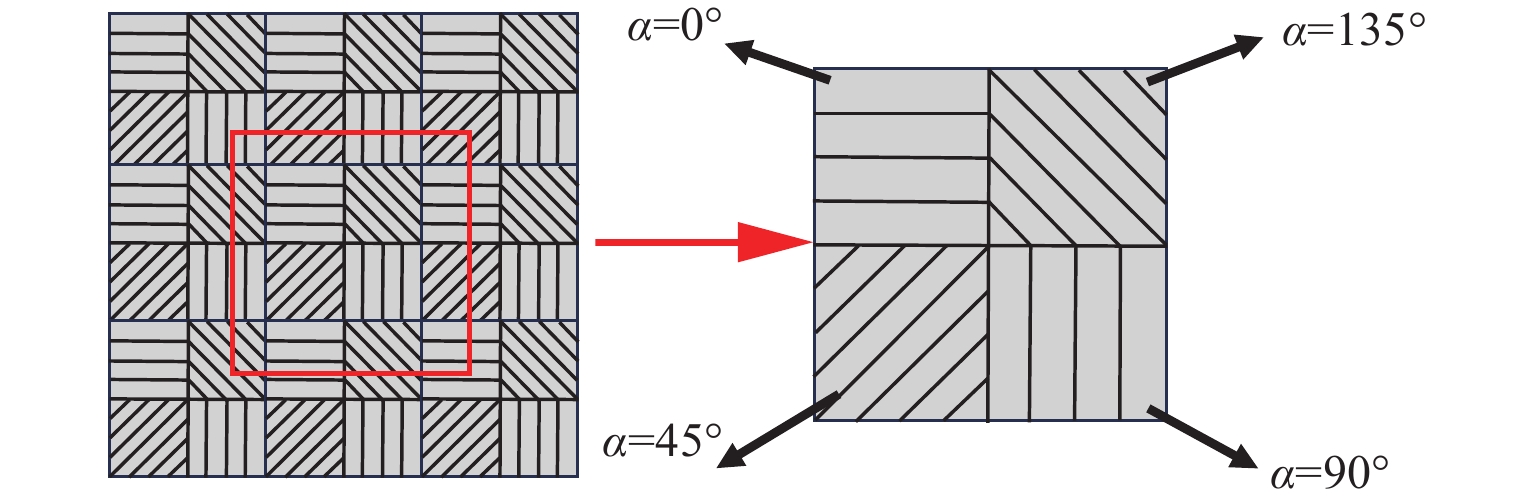
偏振相机等效于在普通相机的靶面前方添加有固定偏振方向和消光比的线偏振阵列,如图2所示,每4个偏振单元为一个整体,以2×2周期排布,从偏振单元中可分别提取4个方向上的偏振信息,组成4幅偏振图像,4个偏振单元之间的偏振方向角度可为0°、45°、90°、135°,由于制作工艺的限制,消光比与理想情况相比存在偏差。同时,入射的波长不等于设计波长时,光线的消光比与理想情况也不相同。式(17)中,线偏振器和偏振相机的Muller矩阵均为理想情况,方位角误差可通过旋转线偏振器进行校正,但是此式并未涉及消光比偏差对测量结果的影响。
由章节1中式(6)可知,考虑消光比误差对测量结果的影响,应该包含线偏振器和偏振相机的消光比。实验中,选用的线偏振器消光比大于5 000∶1,近似为理想的线偏振器[18],因此只考虑偏振相机的消光比带来的影响,即非理想情况下式(6)修正为
$$ {\boldsymbol{M}}_{{\mathrm{P}}2}=\frac{1}{2}\left[\begin{array}{cccc}{\varepsilon }^{2}+1& ({\varepsilon }^{2}-1)\mathrm{cos}2{\beta }_{i}& ({\varepsilon }^{2}-1)\mathrm{sin}2{\beta }_{i}& 0\\ ({\varepsilon }^{2}-1)\mathrm{cos}2{\beta }_{i}& ({\varepsilon }^{2}+1){\mathrm{cos}}^{2}2{\beta }_{i}+2\varepsilon {\mathrm{sin}}^{2}2{\beta }_{i}& (\varepsilon -1{)}^{2}\mathrm{cos}2{\beta }_{i}\mathrm{sin}2{\beta }_{i}& 0\\ ({\varepsilon }^{2}-1)\mathrm{sin}2{\beta }_{i}& (\varepsilon -1{)}^{2}\mathrm{cos}2{\beta }_{i}\mathrm{sin}2{\beta }_{i}& ({\varepsilon }^{2}+1){\mathrm{sin}}^{2}2{\beta }_{i}+2\varepsilon {\mathrm{cos}}^{2}2{\beta }_{i}& 0\\ 0& 0& 0& 2\varepsilon \end{array}\right] $$ (18) 式中$ {\varepsilon ^2} $表示偏振相机的消光比。一般情况,偏振相机并不提供消光比的参数指标,是一个未知量。为了消除偏振相机消光比误差引起的应力测量误差,需设计检测方案,预先求解光路中偏振相机的消光比数据。
具体解决方案为:不加入1/4波片和样品,即让线偏振器件出射的线偏振光直接入射偏振相机,旋转线偏振器件,当偏振相机0°检偏方向接收的光强达到最小值时,得到偏振相机的消光比$ {\varepsilon ^2} = {I_{90}}/{I_0} $,修正偏振相机的Muller矩阵,重新带入式(7)和式(17),可表示为
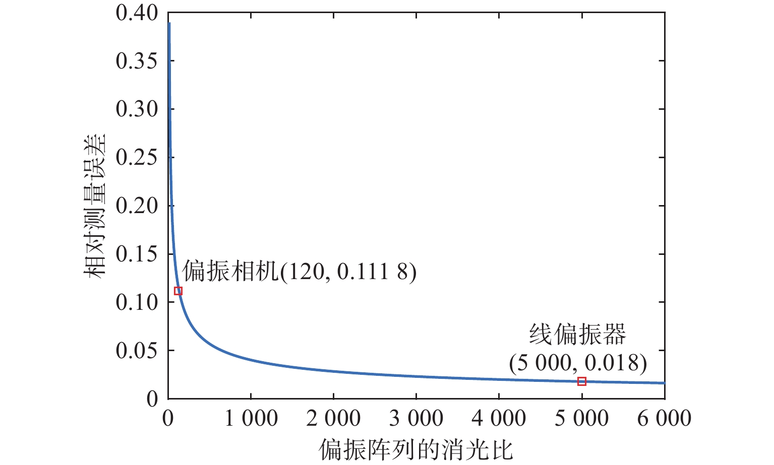
$$ \left\{ {\begin{array}{*{20}{l}} \begin{array}{l} \dfrac{{{I_1}' - {I_3}'}}{{{I_1}' + {I_3}'}} = \dfrac{{{\varepsilon ^2} - 1}}{{{\varepsilon ^2} + 1}}[\cos \delta ({\cos ^2}2{\theta _3} + {\sin ^2}2{\theta _3}\cos \varphi ) - \\ \qquad\qquad\sin \delta \sin 2{\theta _3}\sin \varphi ] \end{array}\\ \begin{array}{l} \dfrac{{{I_2}' - {I_4}'}}{{{I_2}' + {I_4}'}} = \dfrac{{{\varepsilon ^2} - 1}}{{{\varepsilon ^2} + 1}}[\cos \delta \cos 2{\theta _3}\sin 2{\theta _3}(1 - \cos \varphi ) + \\ \qquad\qquad\sin \delta \cos 2{\theta _3}\sin \varphi ] \end{array} \end{array}} \right. $$ (19) 为进一步分析消光比对求取相位延迟的影响,对式(19)中的消光比$ {\varepsilon ^2} $进行仿真分析,当1/4波片的相位延迟不存在误差,即$ \delta = 90^\circ $可以得到偏振相机消光比引起的相位延迟量(与应力值成正比)测量值由$ \varphi $变成了$ \varphi ' $,其表达式分别如式(20)和式(21)所示:
$$ \varphi {'}=\mathrm{arcsin}\left(\frac{{\varepsilon }^{2}-1}{{\varepsilon }^{2}+1}\sqrt{\mathrm{sin}\varphi }\right) $$ (20) $$ \Delta \varphi = \frac{{\varphi - \varphi '}}{\varphi } \times 100{\text{%}} $$ (21) 式中:$ \varphi ' $表示测量得到的相位延迟测量值;$ \varphi $表示真实相位延迟量;$ \Delta \varphi $表示相对测量误差,消光比的相对误差曲线如图3所示。由于线偏振器和偏振相机原理相同,前文选用消光比大于5 000∶1的线偏振器时,引起1.80%的相对误差。此时,检测相位延迟为90°的样品,即使校正了1/4波片相位延迟和偏振相机消光比误差,其相位延迟测量值应该为88.38°。
3 实验测量结果与分析
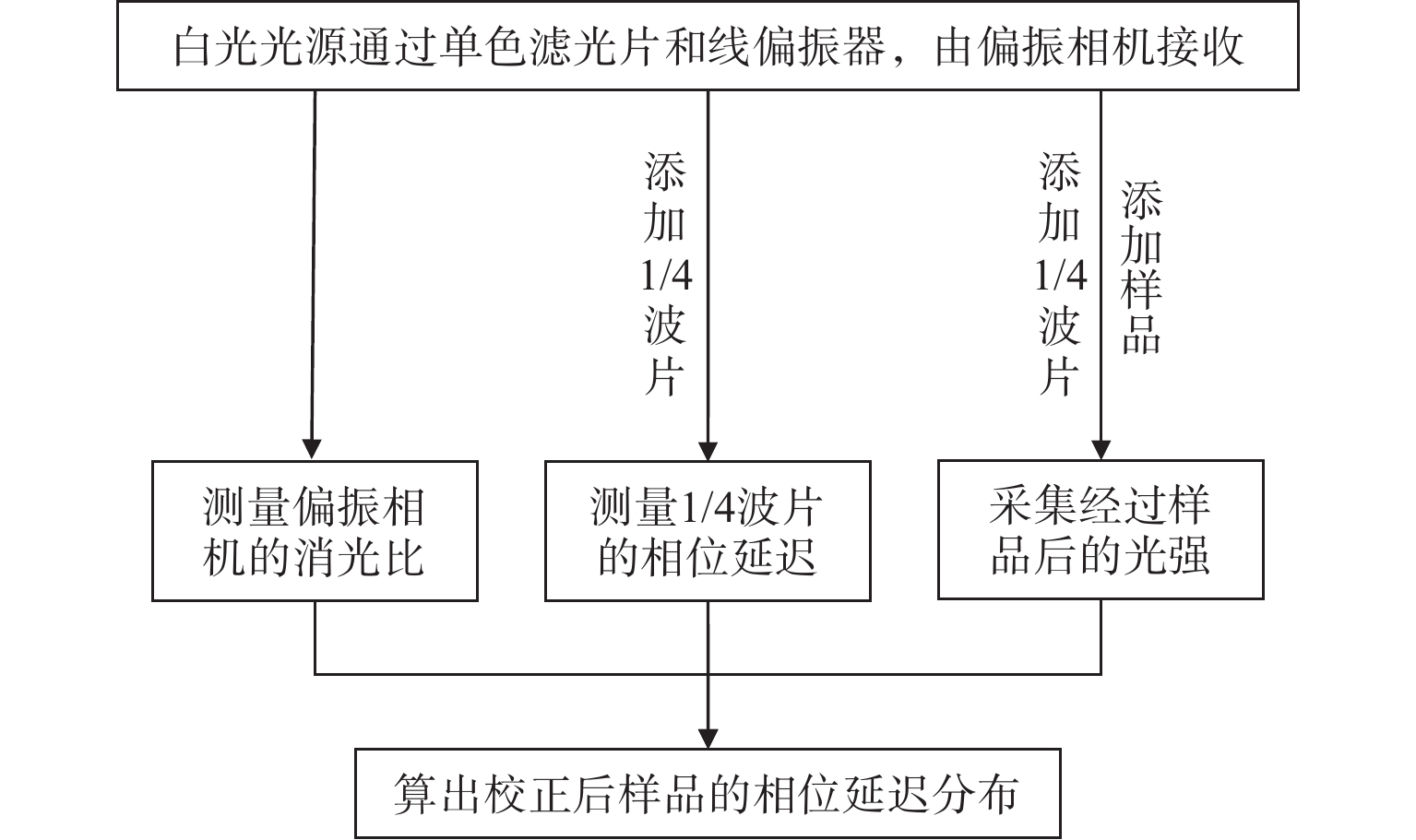
为检验章节2的误差分析和校正方案的可行性,选择美国Thorlabs公司生产、由计量部门赋值的1/4波片作为样品进行实验。波片直径为25.4 mm,在633 nm波段的相位延迟名义值为90°,具体实验过程和误差校正流程如图4所示。
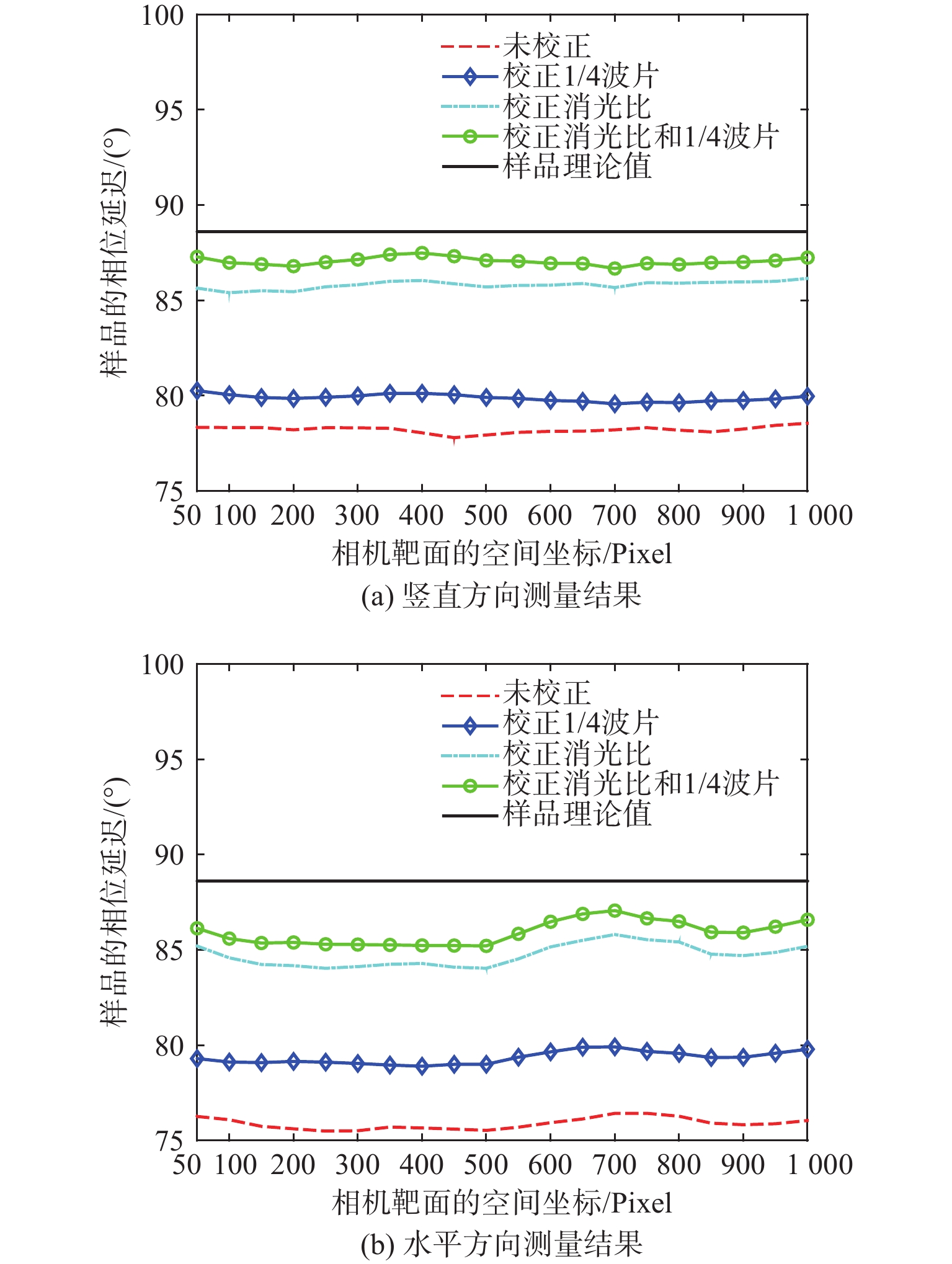
为方便比对,美国Thorlabs公司生产的1/4波片样品,经中国计量科学研究院(以下统称计量院)检测,中心3 mm×3 mm区域的相位延迟平均值为88.60°。本文在校正前后分别测量了该1/4波片在633 nm波段的相位延迟量,分布在分布图的中心区域,结果如图5所示。
![]() 图 5 误差校正前后样品相位延迟测量图Figure 5. Measurement diagrams of sample phase delay before and after error correction
图 5 误差校正前后样品相位延迟测量图Figure 5. Measurement diagrams of sample phase delay before and after error correction由图5可见,校正前竖直方向中心区域样品的相位延迟测量值分布范围为77.89°~78.96°,平均值为78.41°,与计量院测量结果比对,存在11.50%的相对误差。由章节2.1所述在线检测方案,得到前置1/4波片的相位延迟量为88.74°。校正后,重新计算样品的测量值分布范围为79.57°~80.35°,平均值为79.89°,校正后与计量院测量结果比对,仍然存在9.8%的相对误差。同时,由结果看出,1/4波片相位延迟的校正对样品测量结果的影响不超过1.9%,偏振相机消光比误差对测量结果影响更大;仅对消光比误差进行校正,样品的测量值分布范围为85.33°~86.35°,平均值为85.79°,校正后与计量院测量结果比对,测量误差明显减小,但是仍然存在3.17%的相对误差;同时校正消光比误差和1/4波片的相位延迟误差后,样品的测量值分布范围为88.61°~87.66°,平均值为87.06°,与计量院测量结果比对,相对误差为1.73%。结合章节2中图3的仿真结果,可判断出残存误差是由线偏振器的消光比误差引起的。校正前后的测量结果如表1所示。
表 1 误差校正前后相位延迟测量值分布范围与平均值Table 1. Range and average values of phase delay measurement before and after error correction校正参数 竖直方向/(°) 水平方向/(°) 未校正 77.89~78.96(78.41) 77.55~78.66(78.07) 校正1/4波片 79.57~80.35(79.89) 78.82~79.92(79.42) 校正消光比 85.33~86.35(85.79) 84.06~85.86(84.91) 校正1/4波片
和消光比86.61~87.66(87.06) 85.08~87.08(86.03) 计量院测量值 88.60 88.60 4 结论
本文提出了一种基于偏振相机的应力检测和在线误差校正方法,通过理论分析与实验测量,重点讨论了1/4波片和偏振相机消光比误差对样品相位延迟测量的影响。结果表明:当前置1/4波片的相位延迟为90°±3°时,对测量结果影响较小,相对误差不超过1.5%;与1/4波片相比,偏振相机消光比误差影响更大,当消光比低于120∶1时,相对误差超过11%;校正1/4波片和消光比后,相对误差主要受线偏振器影响,当线偏振器消光比高于5 000∶1时,校正后系统的相对误差低于1.8%,若选用消光比更高的线偏振器,能进一步减小误差。
-
![]()
图 5 误差校正前后样品相位延迟测量图
Figure 5. Measurement diagrams of sample phase delay before and after error correction
表 1 误差校正前后相位延迟测量值分布范围与平均值
Table 1 Range and average values of phase delay measurement before and after error correction
校正参数 竖直方向/(°) 水平方向/(°) 未校正 77.89~78.96(78.41) 77.55~78.66(78.07) 校正1/4波片 79.57~80.35(79.89) 78.82~79.92(79.42) 校正消光比 85.33~86.35(85.79) 84.06~85.86(84.91) 校正1/4波片
和消光比86.61~87.66(87.06) 85.08~87.08(86.03) 计量院测量值 88.60 88.60  下载: 导出CSV
-
[1] 肖石磊, 李斌成. 光学元件残余应力无损检测技术概述[J]. 光电工程, 2020, 47(8): 51-61. XIAO Shilei, LI Bincheng. Residual stress measurement methods of optics[J]. Opto-Electronic Engineering, 2020, 47(8): 51-61.
[2] 李阳, 徐均琪, 刘政, 等. 残余应力对介质高反膜面型影响的研究[J]. 真空科学与技术学报, 2021, 41(5): 488-494. LI Yang, XU Junqi, LIU Zheng, et al. Study on the influence of residual stress on dielectric high reflection films[J]. Chinese Journal of Vacuum Science and Technology, 2021, 41(5): 488-494.
[3] MITHILA A. A validated modelling technique for incorporating residual stresses in glass structural design[J]. Structures, 2021, 29: 445-457
[4] 王雷, 许荣国, 阴万宏, 等. 光学元件残余偏振测量方法与装置[J]. 应用光学, 2021, 42(6): 1080-1085. doi: 10.5768/JAO202142.0603004 WANG Lei, XU Rongguo, YIN Wanhong, et al. Testing method and equipment for residual polarization of optical lens[J]. Journal of Applied Optics, 2021, 42(6): 1080-1085. doi: 10.5768/JAO202142.0603004
[5] 潘进, 丁文红, 刘天武, 等. 残余应力的特征与表述形式[J]. 河北冶金, 2020, 28(10): 1-5. PAN Jin, DING Wenhong, LIU Tianwu. Characteristic and expressing modes of residual stress[J]. Hebei Metallurgical Journal, 2020, 28(10): 1-5.
[6] 丁稳稳, 高晓龙, 刘晶. 残余应力检测方法研究现状[J]. 宝鸡文理学院学报(自然科学版), 2022, 42(1): 103-108. DING Wenwen, GAO Xiaolong, LIU Jing. Research status of residual stress detection methods[J]. Journal of Baoji University of Arts and Sciences (Natural Science Edition), 2022, 42(1): 103-108.
[7] TODT J, KECKES J, WINTER G, et a1. Gradient residual strain and stress distributions in a high pressure torsion deformed iron disk revealed by high energy X-ray diffraction[J]. Scripta Materialia, 2018, 146: 178-181.
[8] RAMESH K, SASIKUMAR S. Digital photoelasticity: recent developments and diverse applications[J]. Optics and Lasers in Engineering, 2020, 135: 106186. doi: 10.1016/j.optlaseng.2020.106186
[9] STEFFEN D, CHRISTIAN S, STEFAN K. Digital full-field photoelasticity of tempered architectural glass: a review[J]. Optics and Lasers in Engineering, 2022, 153: 106998. doi: 10.1016/j.optlaseng.2022.106998
[10] 古兆兵, 郝淑杰, 王雷, 等. 一种基于旋转1/4波片法的激光偏振度测量仪[J]. 应用光学, 2018, 39(6): 936-941. GU Zhaobing, HAO Shujie, WANG Lei, et al. Laser polarimeter based on rotary 1/4 waveplate[J]. Journal of Applied Optics, 2018, 39(6): 936-941.
[11] AJOVALASIT A, PETRUCCI G, SCAFIDI M. Measurement of edge residual stresses in glass by the phase-shifting method[J]. Optics & Lasers in Engineering, 2011, 49(5): 652-657.
[12] 李金鹏, 陈磊, 乌兰图雅, 等. 基于移相算法的玻璃应力延迟量快速测量方法[J]. 光学学报, 2013, 33(6): 125-129. LI Jinpeng, CHEN Lei, WULAN Tuya, et al. A method based on phase shifting algorithm for fast measurement of stress retardation of optical glass[J]. Acta Optica Sinica, 2013, 33(6): 125-129.
[13] 高阳, 万新军, 解树平. 偏振相机的透明元件应力测量[J]. 应用光学, 2022, 43(2): 284-290. GAO Yang, WAN Xinjun, XIE Shuping. Stress measurement of transparent elements based on polarized camera[J]. Journal of Applied Optics, 2022, 43(2): 284-290.
[14] 唐凡春, 步扬, 吴芳, 等. 基于径向偏振光的波片参数测量方法[J]. 中国激光, 2022, 49(17): 75-82. TANG Fanchun, BU Yang, WU Fang, et al. Parameter measurement of wave plate based on radially polarized beams[J]. Chinese Journal of Lasers, 2022, 49(17): 75-82.
[15] 万新军, 高阳, 韦晓孝, 等. 圆偏场瞬时光弹相移法的波长失配误差及补偿[J]. 光学学报, 2022, 42(21): 160-167. WAN Xinjun, GAO Yang, WEI Xiaoxiao, et al. Wavelength mismatch error and compensation analysis of instantaneous photoelastic phase-shifting method in circularly polarized field[J]. Acta Optica Sinica, 2022, 42(21): 160-167.
[16] KUSKE A, ROBERTSON G. Photoelastic stress analysis[M]. New York: Wiley, 1974: 132-138.
[17] GOLDSTEIN D H. Polarized light[M]. New York: CRC Press, 2017: 163-167.
[18] 杨洁, 金伟其, 裘溯, 等. 考虑偏振片非理想性的可见光偏振成像修正模型[J]. 光学精密工程, 2020, 28(2): 334-339. YANG Jie, JIN Weiqi, QIU Su, et al. Correction model for visible light polarization imaging considering non-ideality of polarizers[J]. Optics and Precision Engineering, 2020, 28(2): 334-339.
计量
- 文章访问数: 97
- HTML全文浏览量: 12
- PDF下载量: 50

 陕公网安备 61011302001501号